
rigid flex PCBs suitable for aerospace applications
Rigid flex PCBs combine rigid sections with flexible ones in a single circuit board, making them ideal for applications that require the stability of rigid PCBs but also need the flexibility of flexible PCBs. These hybrid designs are used in a wide range of devices, from medical equipment to aerospace systems. They offer the best of both worlds: rigid areas for high component densities and efficiency, while flexible sections provide conformability and dynamic positioning.
rigid flex pcb are designed in three dimensions, which enables them to fold, twist, and form into the desired shape for your product’s package. This spatial efficiency allows for greater design freedom and can be particularly useful in situations where space and weight are important considerations, such as in medical devices.
They can withstand shock and vibration, making them suitable for use in aircrafts and other high-precision electronics. Additionally, they can tolerate environmental conditions that would cause failure of traditional rigid boards, such as UV light, chemicals, oils, radiation, and heat dissipation. This is particularly important in military and aerospace applications, where equipment failure can have life-threatening consequences.
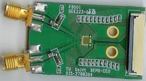
Are rigid flex PCBs suitable for aerospace applications?
Due to their mechanical and electrical characteristics, rigid flex circuits can be more challenging to design than conventional PCBs. There are several critical mechanical and electrical issues that must be addressed to ensure the functional integrity of a rigid-flex PCB. These include:
The minimum bend radius — the distance at which a flex section can be bent without causing damage or affecting performance — is an important design factor. Achieving this requires a careful balance of materials and thicknesses, including the use of stiffeners in some cases. Stiffeners, which are usually made from materials like FR4 or aluminum, can be applied to the flex layers in specific areas where they need additional rigidity.
In addition to a minimum bend radius, the flex sections of a rigid-flex PCB must be designed to minimize stress concentrations, which can contribute to failure. In some cases, this can be achieved by tapering the flex layer thickness or using stiffeners, while in others it may be necessary to incorporate rigid-to-flex transitions into the design.
Other design considerations for a rigid-flex PCB include the maximum number of layers and the use of surface finishes. Increasing the number of layers adds to the complexity of the fabrication process and can lead to increased costs. Similarly, surface finishes can affect the appearance of the final product and impact how well components fit on the board.
A knowledgeable rigid-flex technology fabricator will be able to help you address these and other design challenges. Working with a fabricator early in the design phase can prevent costly errors and rework. It will also make sure that your design is compatible with the manufacturing and assembly processes. This will ensure that your rigid-flex circuit board meets all quality and functional requirements before it goes into production.


